Events
Nov 12, 2021
Free Rhino 3D & Grasshopper Course: Ergonomic Mouse Design

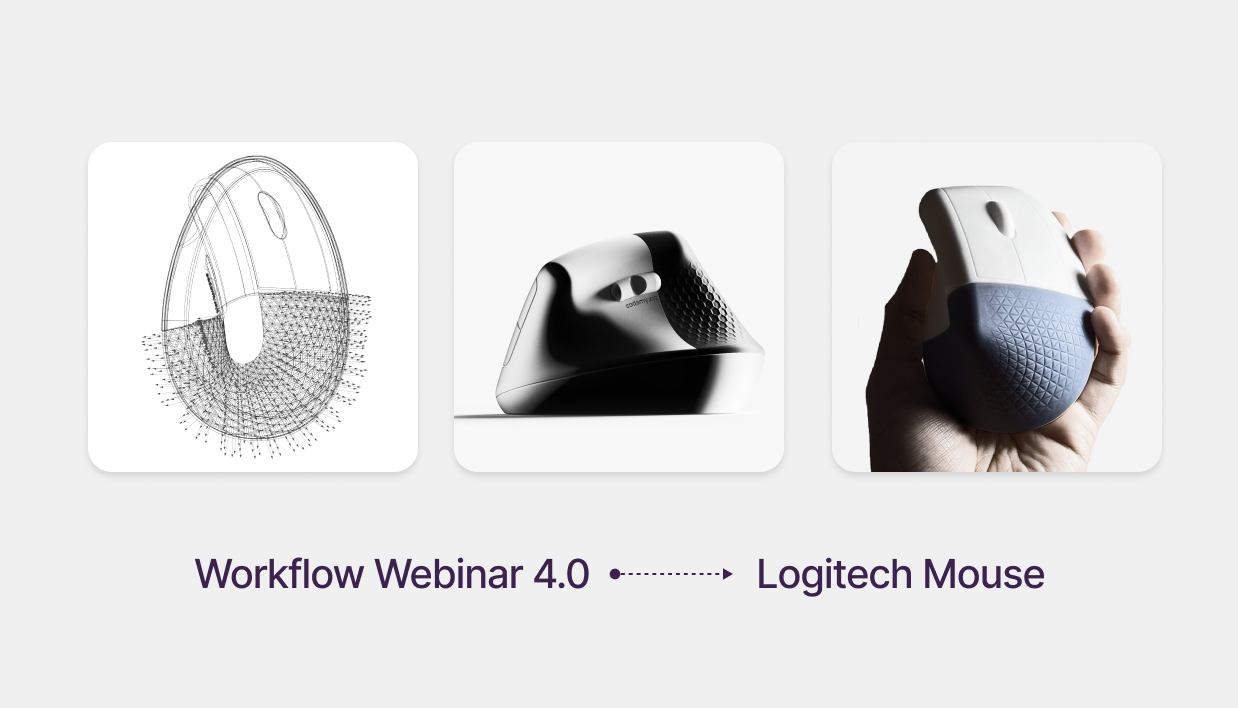
Ergonomic Product Design: Modeling the Logitech Lift Mouse
Free Rhino 3D & Grasshopper Course | Workflow Webinar 4.0
In this session of our free Rhino 3d tutorial, we explore the intersection of ergonomics and computational design. We will CAD model the Logitech Lift—a mouse famous for its 57-degree ergonomic angle—and use a free Grasshopper 3d course module to apply a dynamic, depth-fading triangular grip.
Download Project Files: cademy.xyz/webinar4
You can watch the full webinar here or at the end of this post.
The Logitech Lift is an ergonomic and productivity-focused mouse, designed to reduce wrist strain while offering customizable DPI settings.
According to Design Partners, the MX Vertical mouse was developed through extensive ergonomic research, including:
- Multiple functional prototypes
- User tests measuring muscle strain and activity
- Identification of the optimal 57-degree resting angle to reduce wrist tension
- Achieving 10% less muscle strain and 4x less muscle activity compared to a standard mouse
At Cademy, we will CAD model this mouse and explore parametric texture variations for the grip.
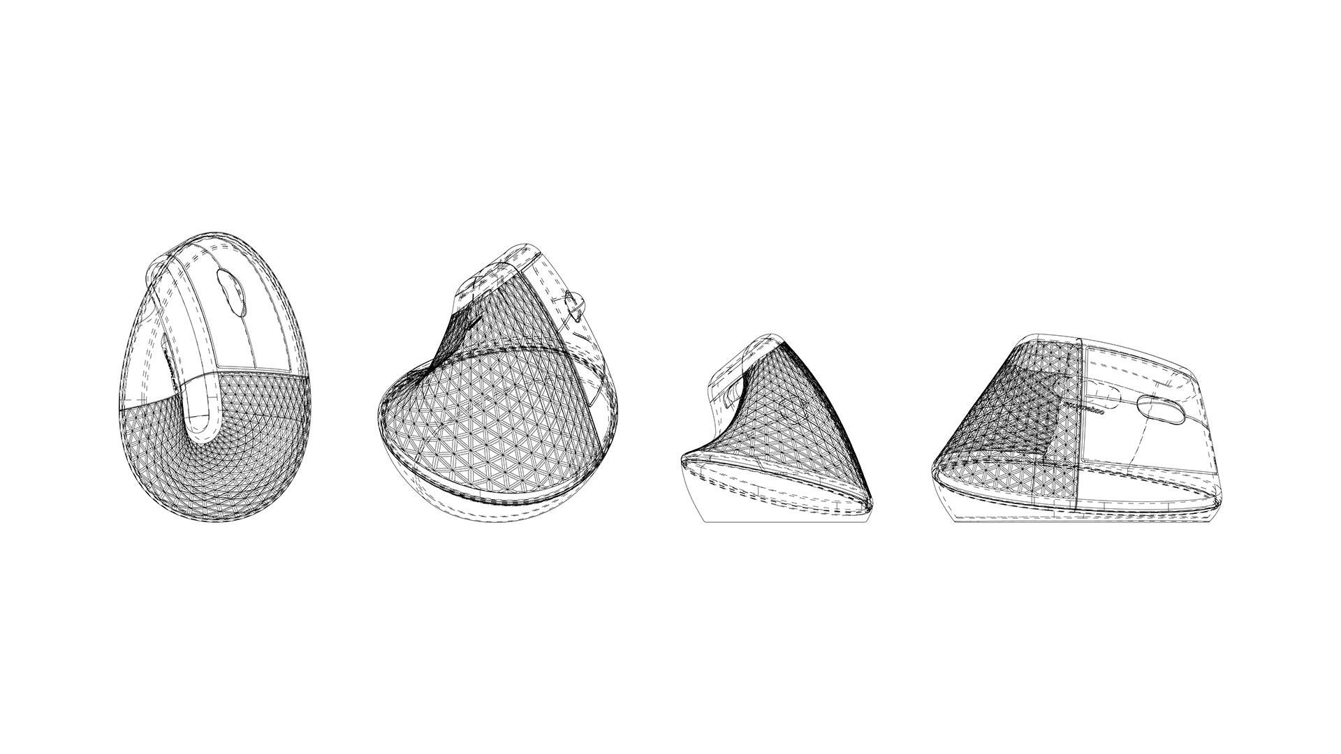
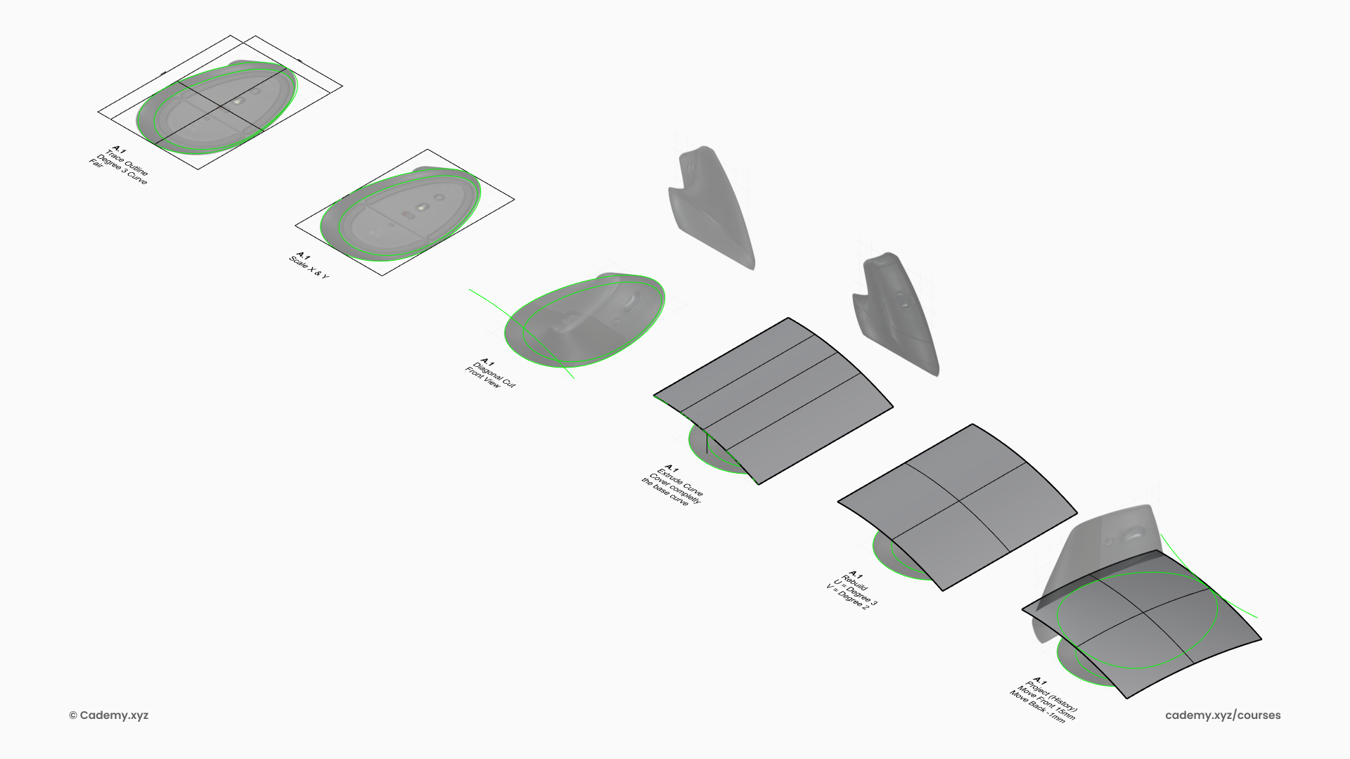
Step 1: 3D Modeling the Base Geometry
- Open Rhinoceros 3D and set up the workspace.
- Draw the Top Profile using NURBS curves based on technical dimensions.
- Create the Lateral Cut Profile and extrude it to form the base shape.
- Rebuild and Deform the extruded curve to project the top profile onto it.
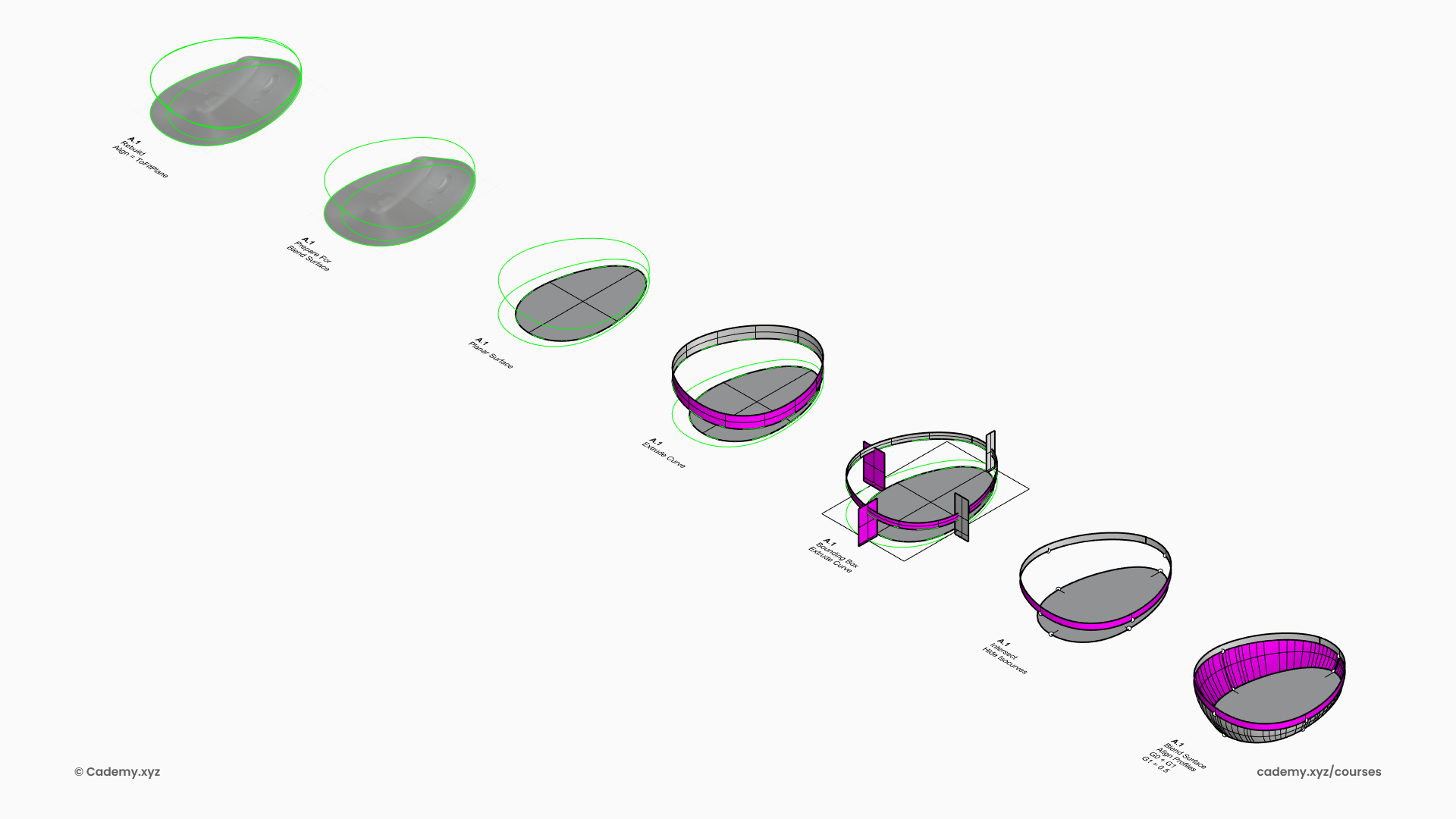
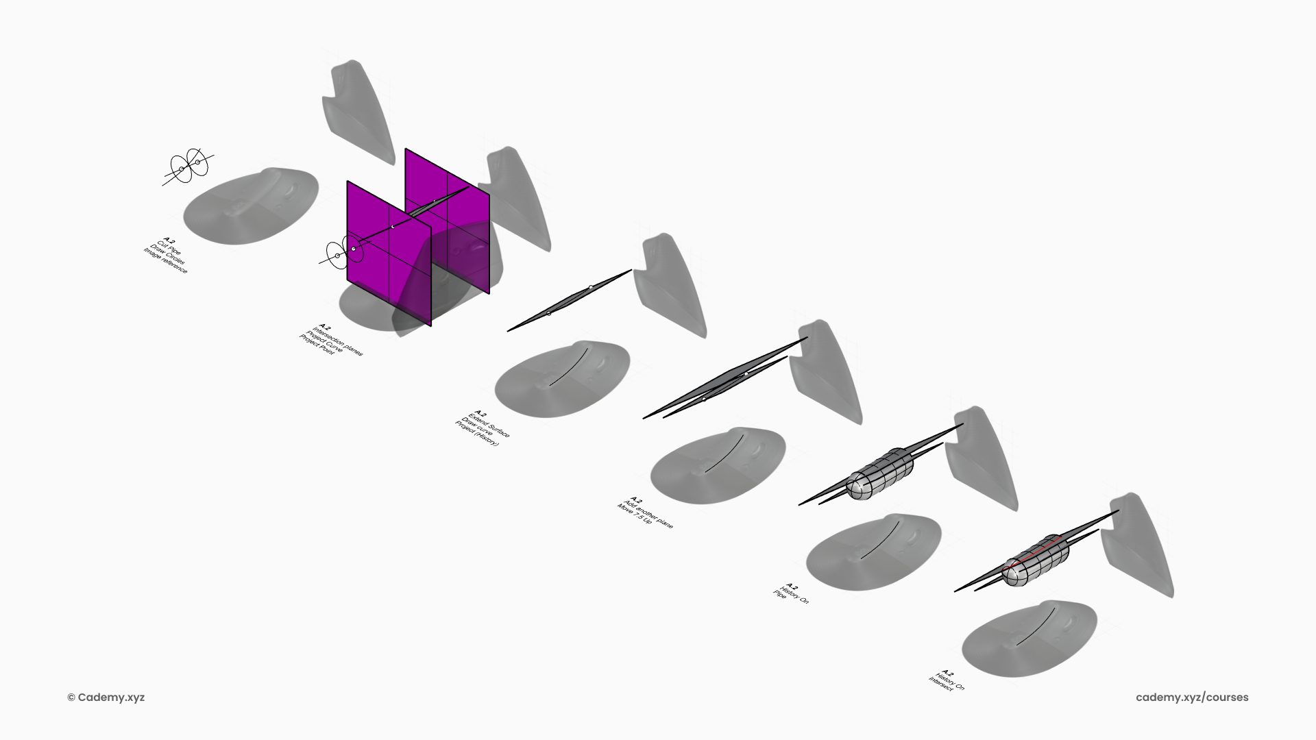
Step 2: Inner Base Profile and Surface Creation
- Convert the Inner Base Profile into a planar (trimmed) surface.
- Extrude the Projected Profile to define the main volume.
- Add Four Intersection Planes to help align the connecting surfaces.
- Blend the Surface using the BlendSrf command with G0 and G1 continuity.
Step 3: Top Part Geometry
- Align Curve Profiles from different views and create the intersection plane.
- Intersect a Plane with a Pipe to generate the upper part of the mouse.
- Trim the Excess Pipe to refine the shape.
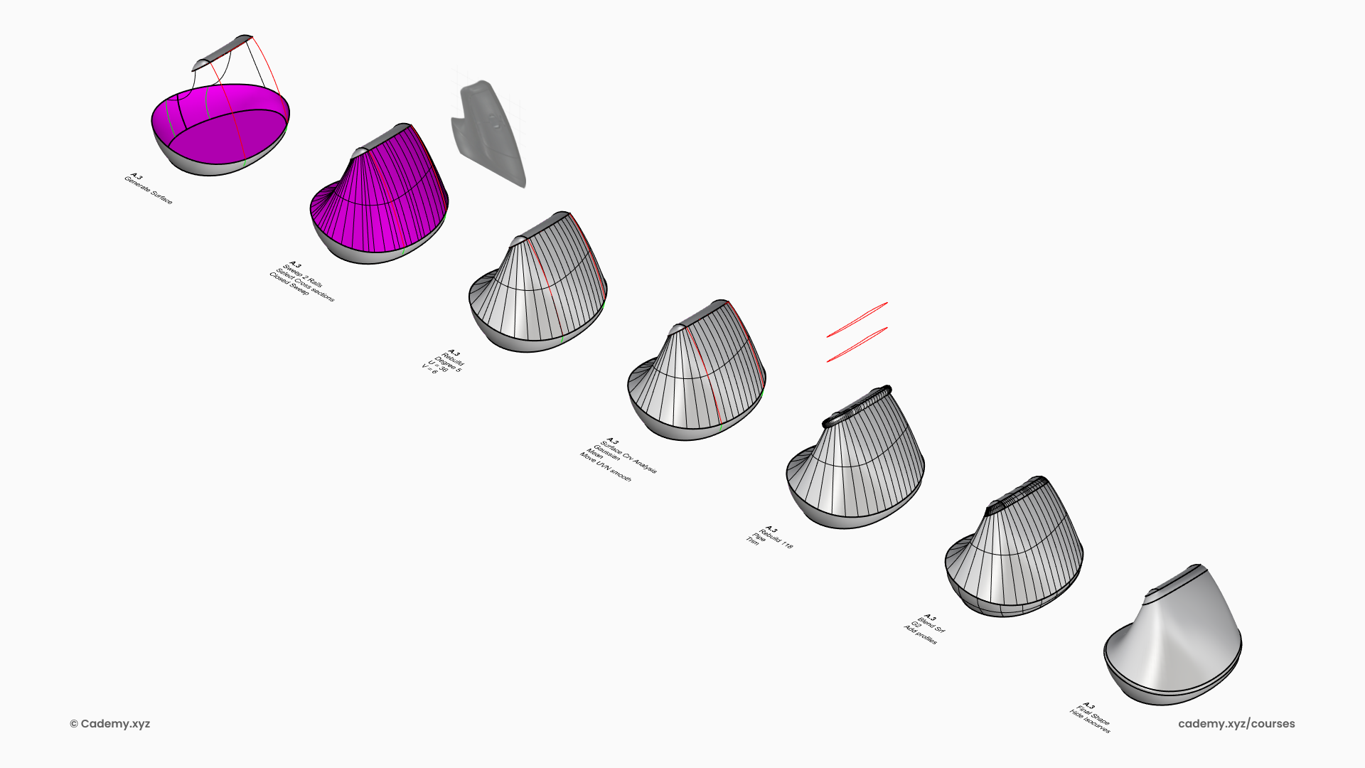
Step 4: Refining the Geometry
- Extend the Pipe Radius and intersect it with the base blend surface.
- Create the Lateral Surface using Sweep 2 Rails with four profiles.
- Rebuild the Sweep to Degree 5 in U & V directions to reduce surface complexity.
- Pipe the Top & Bottom Rail, then trim it from the base geometries.
- Bridge the Trimmed Parts using the Blend Surface command.
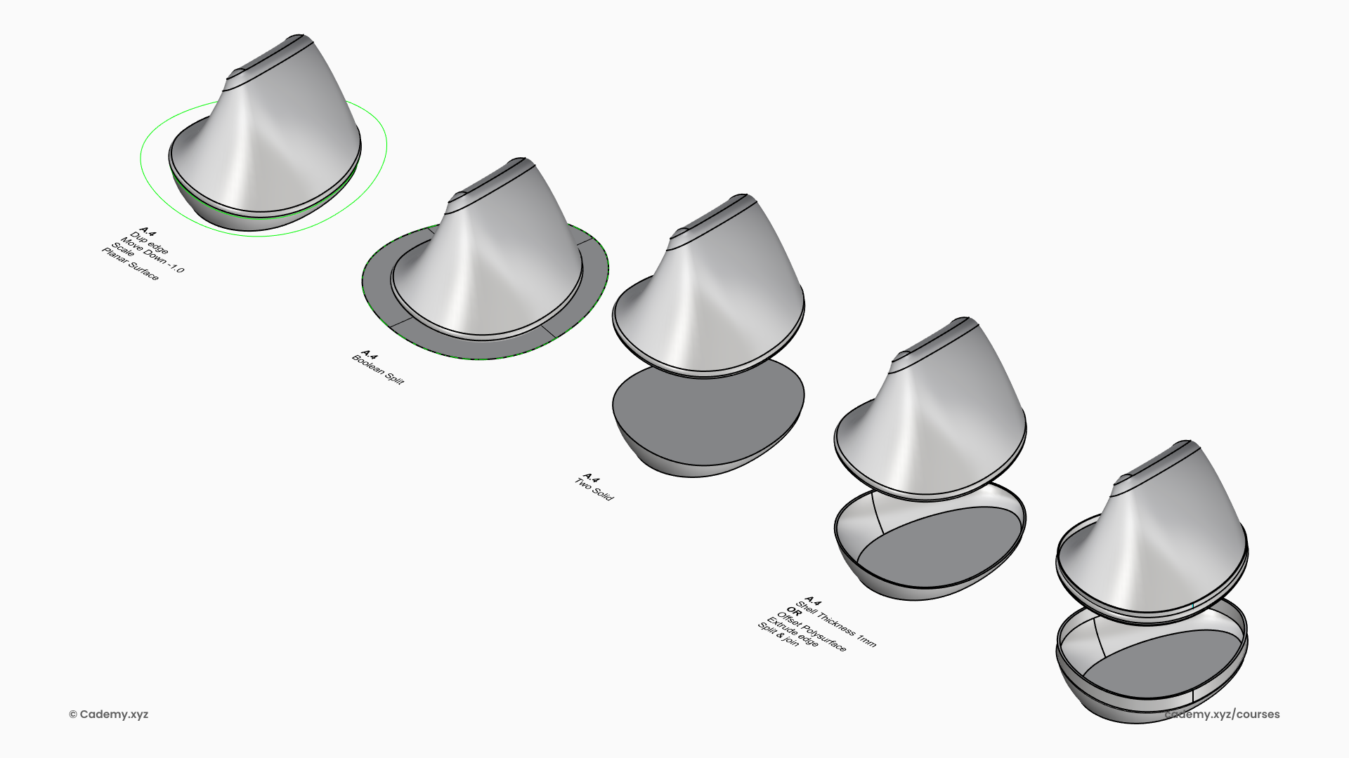
Step 5: Hollowing and Finalizing the Structure
- Boolean Split the mouse to divide it into two halves.
- Apply Shell or Polysurface Offset to give the walls thickness.
- Sweep to Create the Closure Mechanism for final assembly.
Step 6: Mouse Wheel Integration
- Project Curves for Grooves onto the mouse body to define wheel placement.
- Position a Cylinder for the mouse wheel and Fillet the corners to shape it.
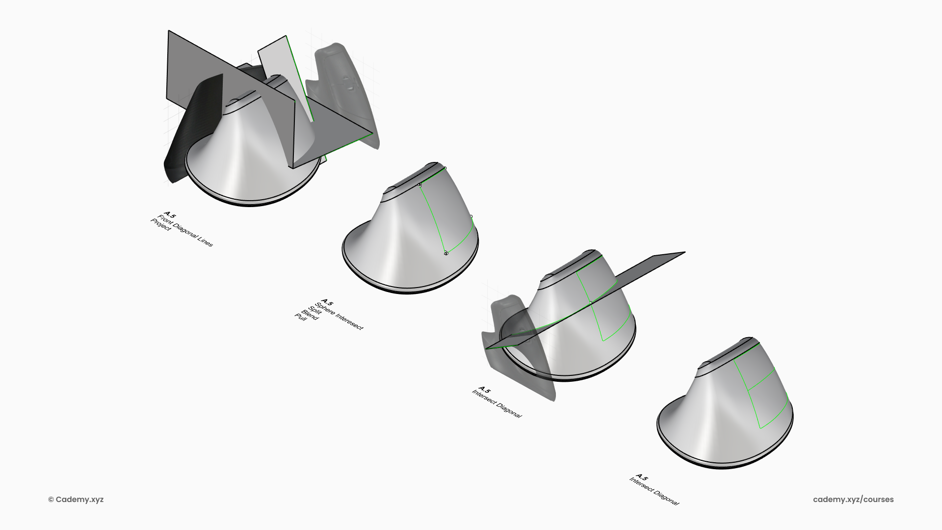
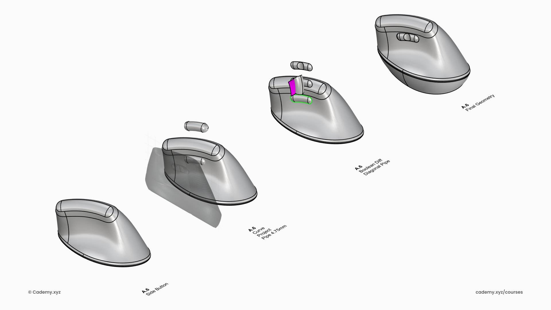
Step 7: Creating the Side Buttons
- Pipe a Profile to define the shape of the side buttons.
- Fillet the Corners for a smooth ergonomic transition.
- Generate a Perpendicular Pipe and split it with the button to refine the form.
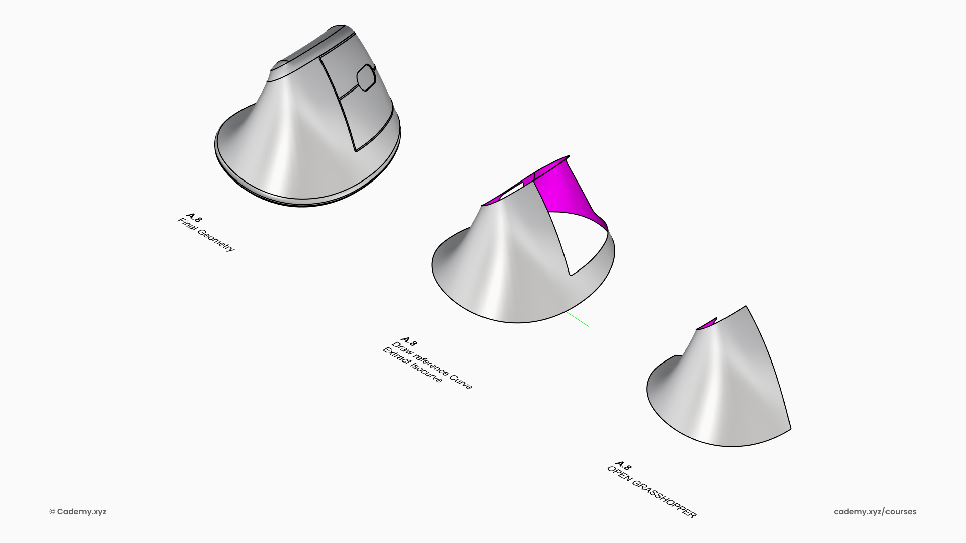
Step 8: Final Geometry Preparation and Texture
- Explode the Polysurface to separate surfaces for texturing.
- Split the Surface with Isocurves to define specific grip limits.
- Import the geometry into Grasshopper to begin the parametric design phase.
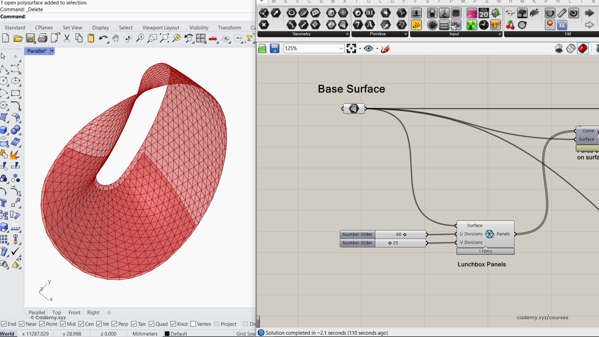
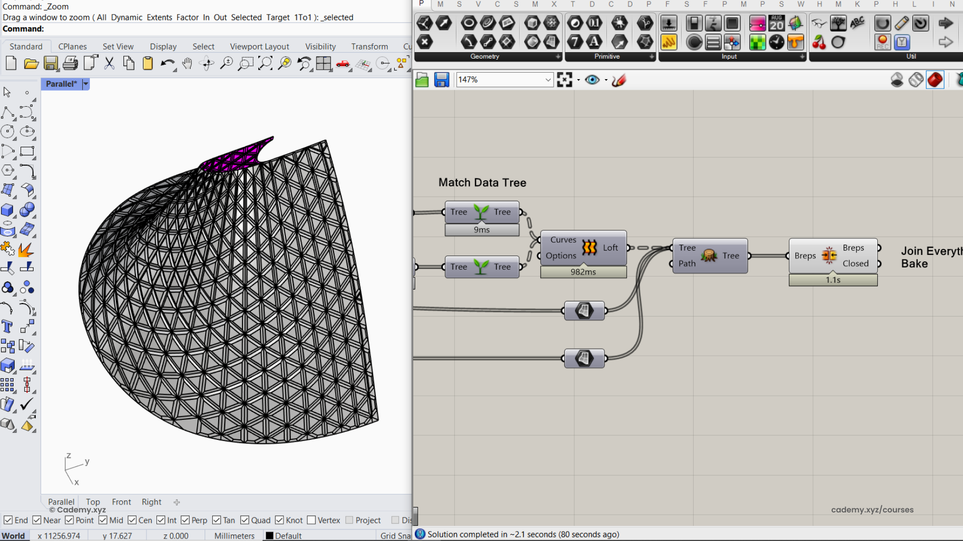
Step 9: Parametric Texture in Grasshopper 3D
- Triangular Paneling: Use the Triangular Panel node on the base surface.
- Untrimmed Extension: Allow panels to initially extend over the entire untrimmed surface for better flow.
- Trim to Fit: Pull curves onto the surface and trim them to match the panel boundaries.
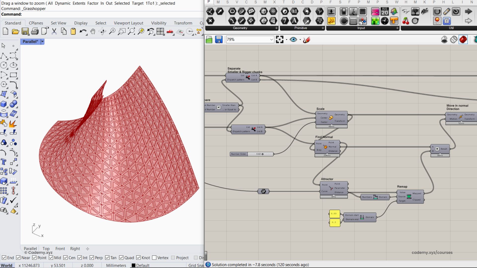
Step 10: Creating Depth Fading Effect
- Naked Edge Attractor: Define the outer edges of the surface as an attractor shape.
- Proximity Scaling: Scale panels based on their distance to the attractor.
- Normal Displacement: Move panels along the surface Normal Direction using attractor parameters to create depth variation.
Step 11: Joining the Panels
- Flatten the List to ensure all elements are processed in a single data stream.
- Join Individual Panels into one continuous, manufacture-ready geometry.
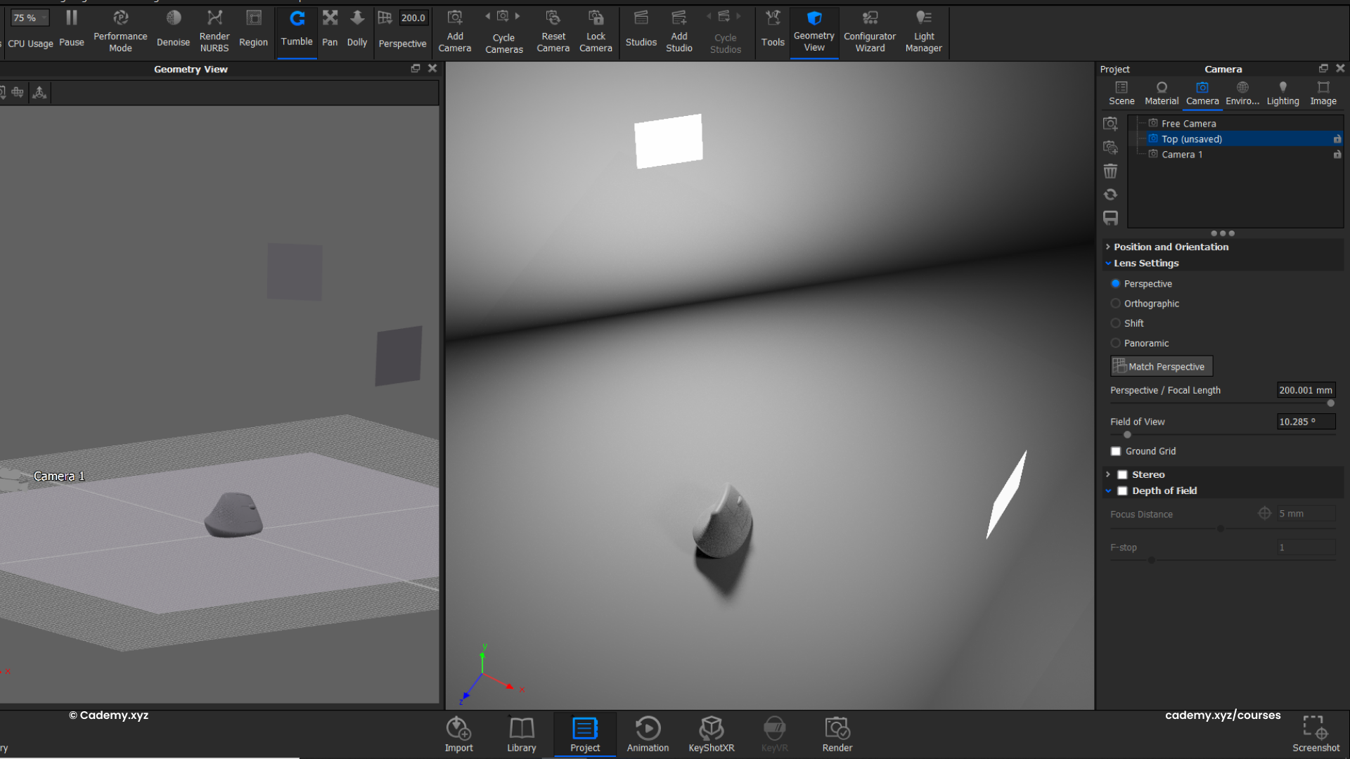
Step 12: Rendering in Keyshot
- Open the native
.3dmfile directly in KeyShot. - Set Up Area Lights using panel geometry to control reflections.
- Adjust Camera & Composition for optimal product framing.
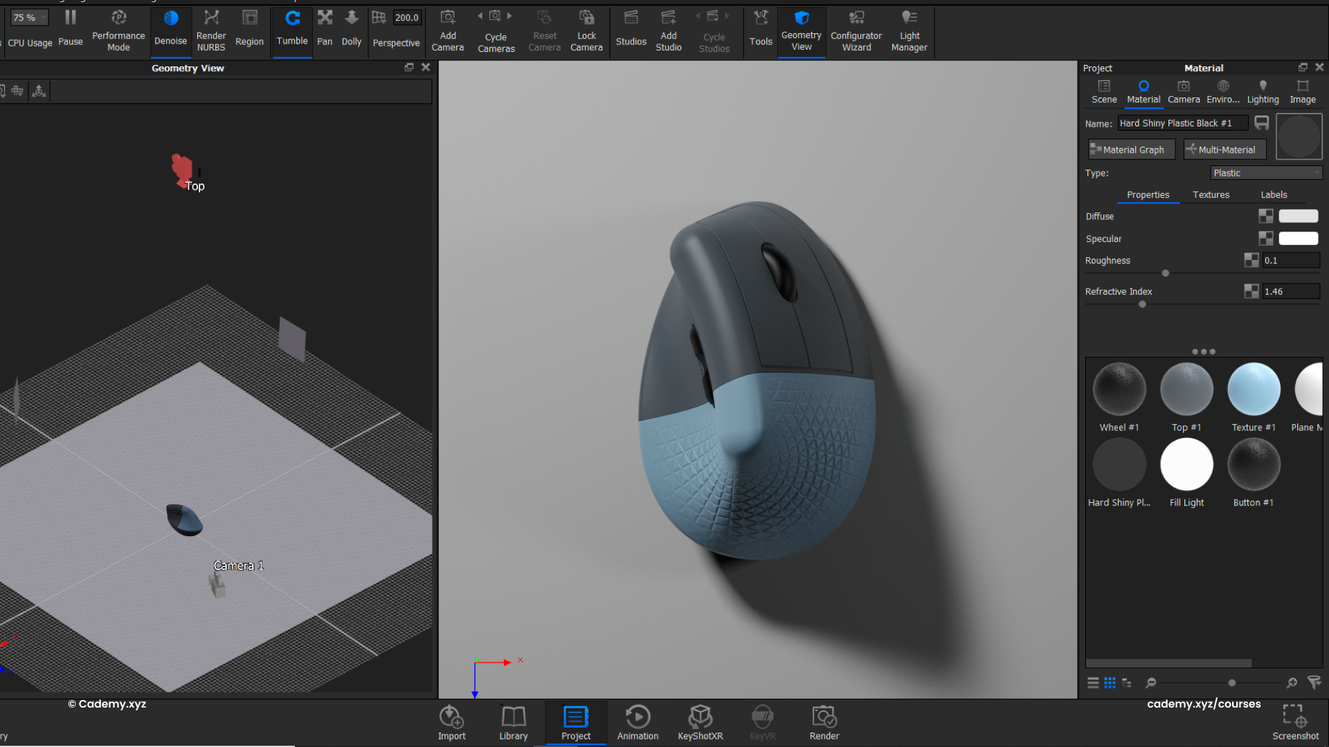
- Apply a hard rough plastic base material to evaluate lighting.
Step 13: Enhancing Material & Lighting
- Apply colorful plastic materials to highlight different design components.
- Select the Product Illumination preset for realistic light bounces.
- Add surface imperfections via the Material Graph for professional realism.
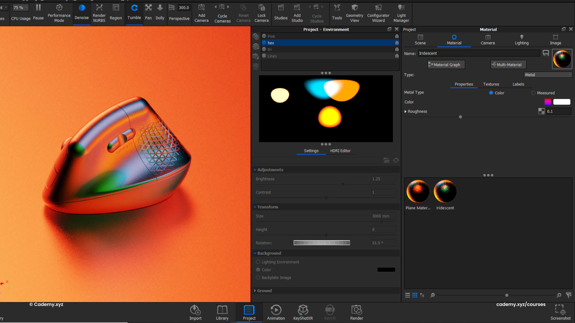
Step 14: Creating Custom HDRI Environment
- Design a custom HDRI with vibrant, colorful lights to emphasize the form.
- Apply a metallic material with an Iridescent Effect to create high-end color reflections.
Workflow Breakdown Summary
- Rhinoceros: Base curve creation, Degree 5 NURBS surfacing, and shell design.
- Grasshopper: Algorithmic paneling, attractor-based depth, and remapping data.
- Keyshot: NURBS data handling, physical lighting, and material graph post-processing.
- 3D Printing: SLA & FDM techniques for ergonomic prototyping.
A. Rhinoceros
- A.1 Image Scaling, Layer Setup & Color Organization
- A.2 Base Curve & Surface Creation
- A.3 Top Curve & Surface Definition
- A.4 Merging & Cleaning (Pipe Fillet)
- A.5 Shelling & Lip Design
- A.6 Detailed Refinements
- A.7 Grasshopper Preparation
B. Grasshopper
- B.1 Basics (Interface, Cables, Reference Geometry)
- B.2 Workflow Overview
- B.3 Paneling for Grip Texture
- B.4 Attractor-based Depth Variation
- B.5 Surface Trimming & Lofting
- B.6 Assembly & Keyshot Preparation
C. Keyshot
- C.1 Introduction (Interface, Environment, Workflow Overview)
- C.2 Model Import & NURBS Data Handling
- C.3 Clay Render Setup
- C.4 Camera Configuration
- C.5 Lighting Setup (Physical & HDRI)
- C.6 Material Assignments
- C.7 Render Settings Optimization
- C.8 Post-Processing (Photoshop Demo)
D. 3D Printing
- D.1 STL Export for 3D Printing
- D.2 SLA & FDM Printing Techniques
Thanks for reading ❤️
