Fix Your Low-Poly 3D Prints: CAD Tessellation for Prototyping

.png)
Fix Your Low-Poly 3D Prints: Mastering CAD Tessellation for Prototyping
The Bridge Between Digital Perfection and Physical Reality
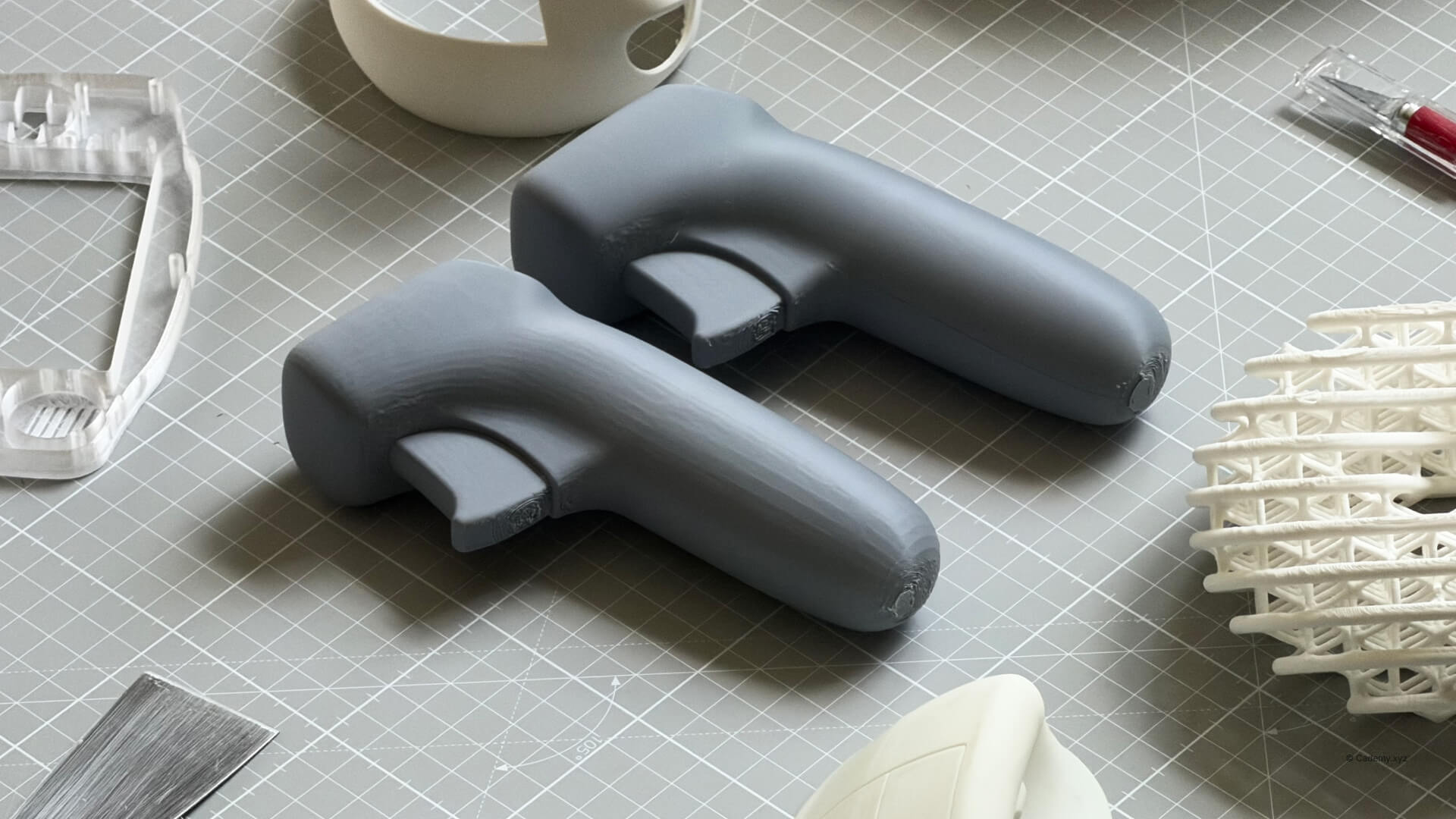
In the world of professional industrial design, your portfolio is only as good as your physical prototypes. When modeling in Rhinoceros 3D or Fusion 360, you are working with NURBS—mathematical representations of geometry that possess infinite resolution.
However, whether you are using a high-end industrial machine or a Bambulab at home, 3D printers cannot read math; they read triangles. When you export your model, the software must convert those smooth surfaces into a Mesh. I have seen countless portfolios where a beautiful CAD model is let down by a "badly tessellated" print—visible jagged faces that ruin the aesthetic of a prototype.
This tutorial is a core component of our Rhino 3D course philosophy: modeling isn't finished until the file is optimized for the real world.
The Logic: Mesh vs NURBS
The density of the polygons (triangles) created during export determines your final quality. Many designers rely on "default" export settings, which prioritize small file sizes. On a high-speed printer like a Bambulab X1C, these defects are amplified.
If your triangles are too large, the printer follows those flat edges. To achieve a "screen-quality" print, we must bridge the gap between Mesh vs NURBS by controlling the tessellation density.
1. Access Detailed Controls in Rhino
To learn Rhino 3D properly, you must move past the "Simple" menus. Select your geometry and use Export Selected > STL. In the export window, click Detailed Controls. By default, Rhino settings are often too coarse, leading to the faceted look seen in amateur prototypes.
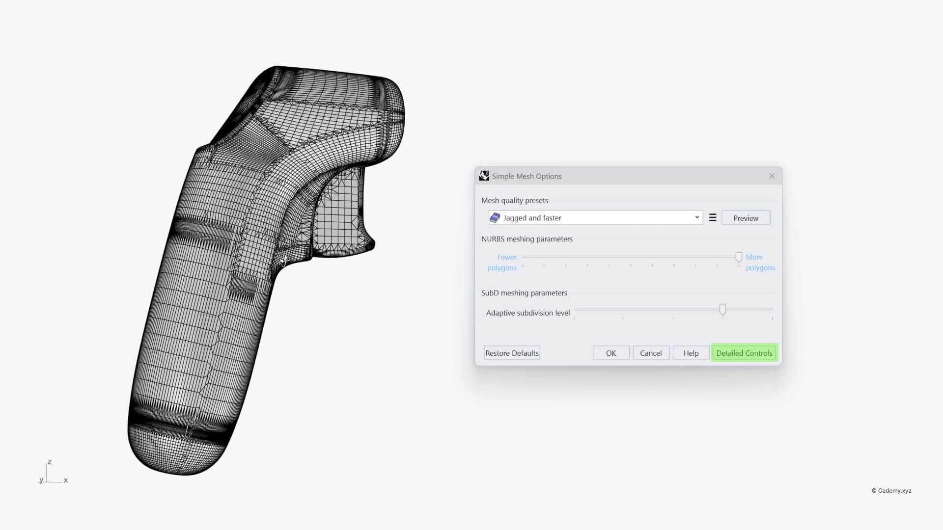
2. The "Bambulab & FDM" Sweet Spot
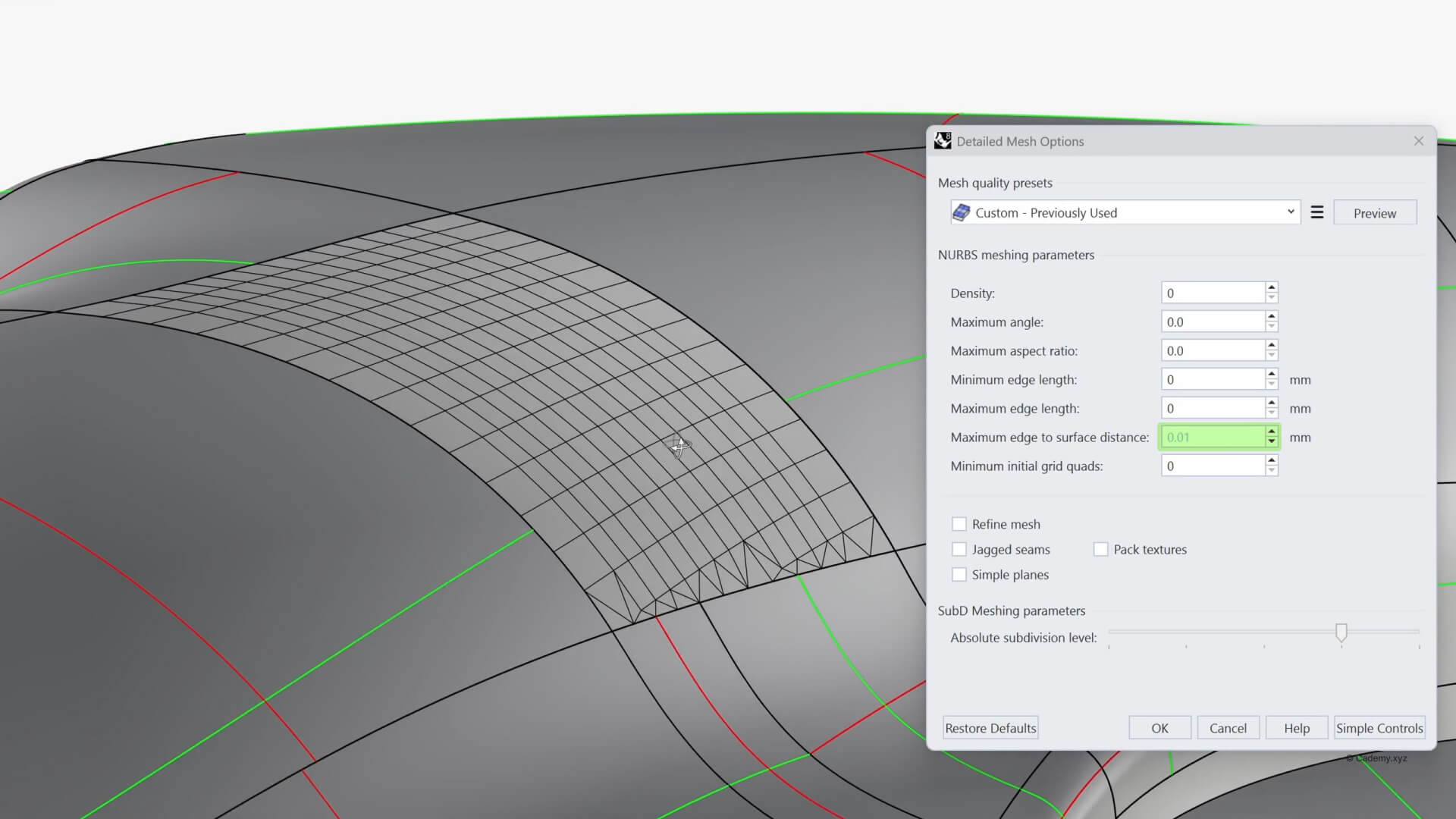
For most makers using FDM printers like Bambulab or Prusa, the most critical parameter is the Maximum edge to surface distance.
- Target Value: Set this to 0.01 mm.
- Why? This provides a perfect balance. It is precise enough that the human eye cannot see the facets, but it won't make the file so heavy that your slicer crashes.
3. SLA and High-Detail Prototyping
If you are building an industrial design portfolio that requires resin (SLA) prints, you need even more precision. Because resin printers have a much smaller pixel size, set your distance to 0.001 mm. This ensures your prototype feels like a finished product, not a 3D print.

4. Improving Your Rendering Workflow
This isn't just for printing! If you’ve noticed jagged silhouettes in KeyShot or V-Ray, it’s a tessellation issue. Use these same principles when importing your Rhino files into rendering software to ensure your highlights and shadows wrap perfectly around your surfaces.

5. Fusion, Solidworks, and Other CAD Packages
This isn't a problem unique to Rhino. The exact same mathematical logic applies to any NURBS-based CAD package. If you are modeling in Solidworks, Fusion 360, NX, Alias, Catia, or Creo, your software is doing the exact same translation from smooth math to flat triangles upon export.
The Rule of Thumb: No matter the software interface, find the option that controls the distance/deviation between the mesh and the original surface geometry, and set it to our recommended target values.

Final Thoughts
A professional prototype requires attention to detail at the export stage. By taking control of your tessellation, you ensure your physical work matches your digital skill.
